
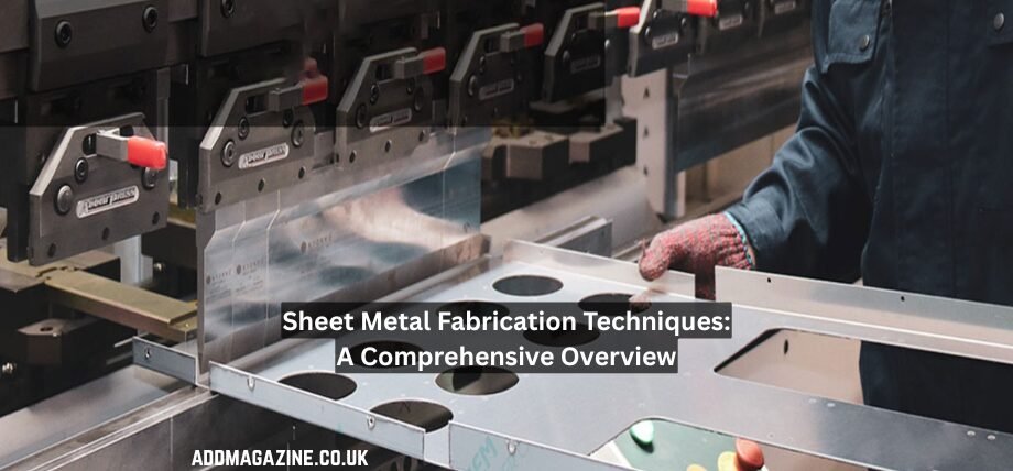
Sheet metal fabrication is the process of manufacturing components by shaping and cutting metal sheets using many sheet metal fabrication techniques, such as laser cutting and bending. Sheet metal fabrication mainly relies on forming metal sheets using mechanical force, fabrication, and joining to achieve structural integrity.
Material Selection in Sheet Metal Fabrication
Material selection is crucial when using sheet metal fabrication techniques because it determines the properties and cost of the parts. I have seen that structural jobs use carbon steel because carbon steel gives strength.
Aluminium is commonly chosen for lightweight components because it combines low weight with effective heat transfer, while copper sheets are preferred for electronic parts that demand stronger electrical conductivity.
Choosing the right material depends on several performance characteristics, including its strength under load, ability to stretch, and overall thickness. An example is that austenitic steel, such as 304, offers excellent ductility but is more expensive than mild steel.
| Material | Example Grades | Typical Yield Strength (MPa) | Main Characteristics | Common Uses | Forming Ability | Relative Cost |
|---|---|---|---|---|---|---|
| Carbon Steel | S235, ASTM A36 | 235–350 | Strong, easy to weld, and magnetically responsive | Support structures, cabinets, fabricated assemblies | Good | Low |
| Stainless Steel | 304, 316 | 200–300 | Resists corrosion and offers a clean, durable surface | Food machinery, healthcare equipment, processing systems | Excellent | High |
| Aluminium | 5052, 6061 | 180–250 | Low weight with good resistance to oxidation and corrosion | Vehicle components, aircraft panels, lightweight housings | Excellent | Medium |
| Zinc-Coated Steel | DX51D+Z | 140–300 | Protective zinc layer helps reduce corrosion and weather damage | Ventilation systems, roofing sheets, exterior components | Good | Low–Medium |
| Copper | C101, C110 | 200–300 | Conducts heat and electricity efficiently and has natural antimicrobial qualities | Electrical conductors, thermal systems, heat-transfer parts | Excellent | High |
| Brass | Cz121 | 300–500 | Easy to machine with an attractive gold-toned appearance | Valves, fittings, fixtures, decorative components | Good | High |
Cutting Techniques for Sheet Metal Fabrication
Sheet metal production relies heavily on precision cutting. Whether using lasers or waterjet cutters, these sheet metal fabrication techniques ensure that raw material is prepared for sheet metal machining.
Laser Cutting
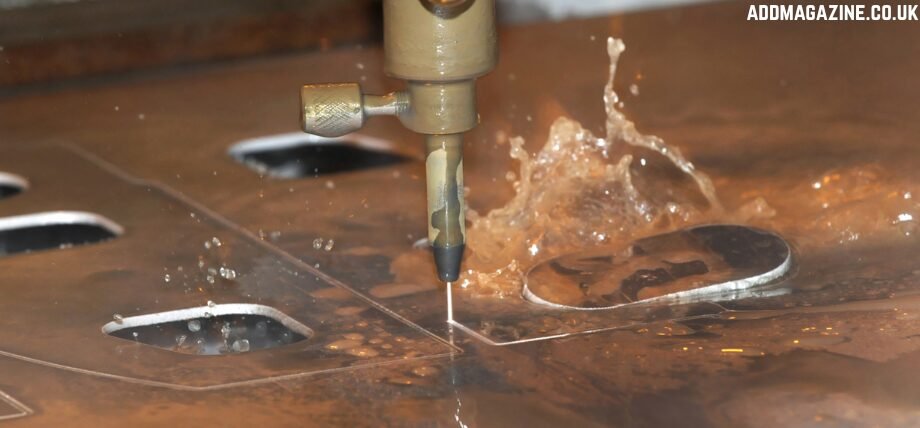
Cold-process waterjet cutting
Laser cutting uses CO2 and fibre lasers to heat the metals to high temperatures that melt the metal along a programmed path. Oxygen is used to increase the temperature for a cleaner and more efficient cut, while using nitrogen minimises oxidation during cutting and cleans away molten slag.
The kerf width of laser cutting varies depending on the material’s thickness and the beam quality, typically ranging from 0.1 to 0.5 mm. Fibre lasers are better at cutting shiny and reflectiv e material such as copper due to their 1μm wavelength absorption.
For large-scale sheet metal manufacturing, this cutting method can process mild steel up to 25 mm thick and stainless steel up to 20 mm thick. Tolerances can be as low as ±0.1 mm, with a small heat-affected zone (HAZ) under 0.2 mm, which preserves the structural integrity.
Waterjet Cutting
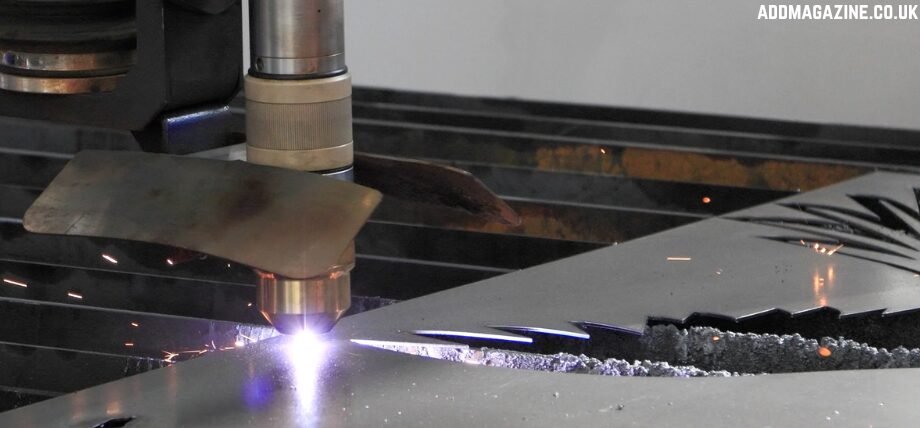
Precision fiber laser cutting
Wajerjet cutting utilises high-pressure water combined with abrasives to cut through hard materials. Water reaches pressures of up to 620 MPa as it passes through an extremely narrow 0.25–0.4 mm opening made from sapphire or diamond. The narrow opening forces the water into a concentrated jet, allowing it to reach velocities of more than 900 m/s.
Kerf widths typically fall between 0.8 and 1.2 mm, allowing the cutting process to maintain dimensional accuracy within approximately ±0.1 mm.
This waterjet does not generate any heat, which removes HAZ and related factors, such as thermal expansion and material hardening. This makes the process easy for you to implement for precision sheet metal machining with heat-sensitive metals.
Plasma Cutting
Plasma cutting works by using a high-temperature arc that can reach temperatures above 20,000°C to ionise gas. The ionisation forms plasma, which is further used to cut conductive materials.
The torch range depends on the gauge of material you want to cut. Typically, 30 A is used for thin gauges and can go all the way up to 800A for thick plates. The krd width is 1.5-4 mm and forms dross on the underside that needs to be cleaned.
The plasma cutting process is highly precise with a tolerance of ± 0.5mm and a maximum cut depth of 50mm for mild steel. The quality of the cut generally decreases after 30mm, which makes it ideal for you to cut around the 30mm width.
You can reduce the bevel angle of the plasma cutter down to 3° by using high definition system that has precise gas controls.
Bending and Forming
Press Brake Bending
Press brake bending works by exerting force by a punch onto a V-shaped die that creates a bend with precise radii. The spring back of the material mainly depends on its yield strength and grain direction, and can be adjusted for by over-bending it by a few degrees (1°-5°) to achieve precision.
To avoid distortion, the minimum flange length is 4 x thickness + bend radius. Modern manufacturers use CNC hydraulic presses and advanced sheet metal fabrication techniques to allow you to achieve repeatability with a precision of ± 0.1° with large lengths up to 6m.
Deep Drawing
Deep drawing is a straightforward process that can yield excellent results. It works by using a punch to force a blank into a die cavity. During the opening stage, the draw ratio typically falls within a range of approximately 2.0 to 2.2.
The wrinkling that occurs during the process is controlled by a blank force, which is the force with which the holder clamps the materials blank and is typically around 1-3 MPa. The thinning occurs maximally at high-force areas, such as the punch radius.
Using a lubricant, such as polyethene film, can reduce friction and therefore reduce heat. Redrawing multiple times allows you to exceed the drawing ratios. Beverage cans and fuel tanks are prime examples of redrawing.
Die Stamping
Die stamping involves progressive, transfer and compound operations using hardened tool steel dies. Throughout the sheet metal manufacturing industry, progressive dies perform the stamping process in a series of steps, starting from punching, followed by bending and lastly forming.
The process allows for rapid sheet metal production and can achieve a rate up to 1500 strokes per minute. The forces used to stamp depend on the material thickness and can range from 50 -5000KN. The clearance for punching is typically around 5-10% of the thickness per side for shearing
Additionally, you can improve the longevity of the tools beyond 100,000 hits by using proper lubrication and TiN coating.
Punch Die
Punching is used to create internal and external features in components and parts. The process uses a single station or turret press to imprint the features onto the parts. In sheet metal machining, factors such as punch to die clearance can affect the burr height and edge quality.
Modern high-speed presses can reach speeds up to 1000 strokes/min for small holes. Larger contours and features are made with the help of niuibling, which helps to approximate the shape of the feature. Multiple features are produced at the same time using Cluster tools, while extrusion pinching makes raised collars for threading.
Finishing
Deburring
Deburring is the process of cleaning up the final component by removing sharp edges and points that form during cutting. Manual methods of deburring that are normally used are filing and abrasives.
Large quantities are finished by using a technique called tumbling, where a vibratory tumbler with ceramic media polishes the parts and components. The process reduces Ra from 6.3 μm to 1.6 μm in 4–8 hours.
Electrochemical deburring is used to deburr complex internal features. It works by dissolving the burrs anodically in salt solutions without the need for any mechanical stress.
Powder Coating
Powder coating works by applying thermoplastic powders electrostatically, such as epoxy and then curing them at 160–210°C for 10–20 minutes. The thickness of the film can range from 50-150 μm, which covers all the recesses evenly.
Powder coating has great durability with impact resistance over 160 inch-pounds and over 1000+ hours of salt spray resistance, which complies with ASTM B117.
Anodizing
Anodised finishing is a porous finish that is an oxide layer made by treating the metal with sulphuric acid electrolysis for a type II finish. The procedure involves dipping the metal in sulfuric acid at 0–5°C while passing an electric current that has a density of 1-2 A/dm².
The anodised coating can reach a hardness level of 500 HV, and to enhance corrosion protection nickel acetate seal is used.
Conclusion
Sheet metal cutting is a broad and versatile process that incorporates various sheet metal fabrication techniques to make precision components. Using the right technique for the material allows you to create high-strength components that last and have op[timnal parameters that suit a wide range of engineering applications.